Why choose Huebner Electric LLC to program your machine controls
Huebner Electric PLC programing logic is written easy to understand. No masks, no bit shifts, no indirect addressing. Outputs are not grouped or transferred as a "Word". Anybody able to understand basic ladder diagrams can easily follow Huebner PLC logic. If an output is not turning "ON", right-click on the output, search, and the line of logic that controls the output is displayed.
Huebner will never set or transfer outputs as a "Word". If a program transfers outputs as a word, when the output is right-clicked there will be a message, "Not found" - which adds another obstacle to finding the problem.
Programs are easy to understand, logic is easy to follow, to reduce help calls. Output is not turning "ON" - easily search/follow logic searches/reversing back through the program to find the missing input.
HMI programs have a screen describing conditions required to switch each individual output "ON". If an output is not turning "ON" There will be a message screen on the HMI describing what inputs are required for the output in question to be "ON". Each output will have a dialog describing the conditions required to set the output High. In most cases the operator is able to solve the problem without having to call for an electrician when the problem input is displayed for the operator.
HMIs have inputs screens showing the status of each input, ON or Off, in real time, for verifying sensor inputs. Image below is an example.
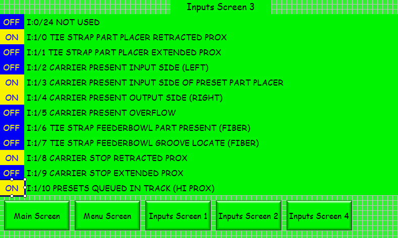
The above screen is a C-more 7" HMI
The same type HMI screens for outputs.
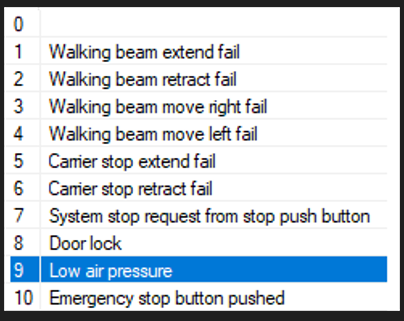
If the PLC program is written as a "State" machine, there will be a HMI screen for each state as a list of on/off indicators, in real time, which must be either On or Off before the machine can transition to the next state.
The image below shows the conditions required to satisfy all the required conditions to transition to the next state.
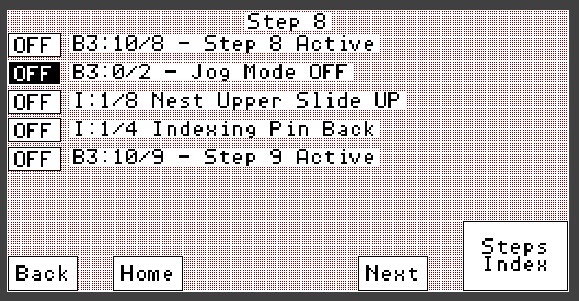
The above image is for an A-B 550 touch screen.
State Logic:
A machine may have more than one state machine operating in the PLC. Each state register is displayed on a HMI screen. If a machine stops, one can go to the state the machine stopped at so see what condition is not being met to advance to the next state. In the above image, each bit must transition to dark background to meet requirements to satisfy the state. When the top four indicators are satisfied the bottom indicator is set true, the machine goes to the next state.
Note:
If a "state" programmed machine errors/stops in the middle of a state, the error must be addressed before restarting operation. If an operator moves machine parts while trying to fix the problem. There is a possibility the operator could unknowingly move something out of position required for the machine to advance. All parts must be in the correct place for the machine to advance to the next state. A state requirements list screen on the HMI allows one to readily see which sensor is not being made to satisfy the current state requirements.
Alarms:
An alarm message on HMI is displayed as a persistent text message. An example is an over-travel alarm. Acknowledge or reset will not clear the alarm. An alarm screen created by a typical programmer will not allow navigating to manual functions screen on the HMI. The problem could be solved by navigation to a manual operation screen and manually move the over traveled component back into range. Quite often an "Alarm" screen seems like an appropriate solution to a typical programmer. Unfortunately the typical "Alarm" screen function locks-up/freezes the HMI so the machine has to be shut down and one must physically move the over traveled component back within range. No alarm will prevent screen navigation to a manual operation screen in a Huebner programmed HMI.
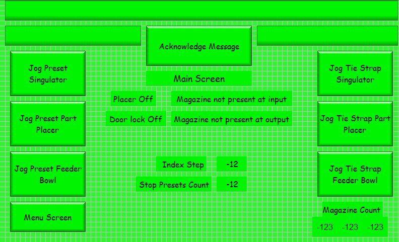
The image below is a main HMI screen of machine running with no errors.
The image below is a main screen displaying alarms.
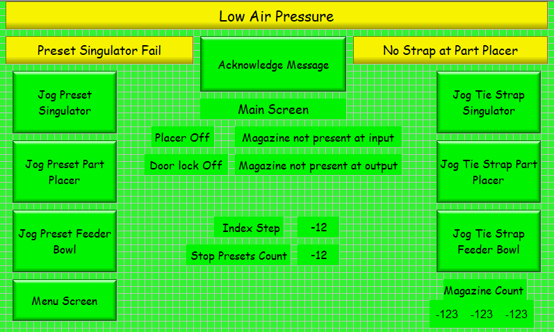
Below is an image of possible main alarms.
Huebner Electric creates wiring diagrams in AutoCAD.
A technical manual is created for operators and an additional manual for maintenance if needed.
Manuals will include illustrations where needed.
Sourcing sensors are preferred. Sinking sensors are installed if customer prefers.
24VDC open collector outputs are preferred. Triac outputs for 120VAC devices.
Optically isolated relays are installed for outputs requiring high current loads.
Fuse monitoring for inputs and outputs is possible.
If a critical circuit fuse opens the machine is emergency stopped to prevent damage to the machine.
In some cases the machine controls have been designed by a professional engineer for critical personnel safety. If machine control is critical for life safety - the controls cannot be changed - only monitored. For example - a punch press controlled by relays.
A PLC with HMI can monitor an existing machine operation without changing existing machine controls. Machine inputs are parallel connected to PLC inputs. Existing machine outputs are also connected to PLC inputs. The only output of the PLC is to emergency stop the machine if it detects a crash is imminent or critical output fuse opens. The PLC output is connected in series with the existing emergency stop circuit. The main purpose of the PLC HMI installation on an existing relay logic machine is to monitor machine operation and diagnostics - not control the machine.
Return to Home Page
Contact Huebner Electric LLC: ron@ronhuebner.us
Phone: 360-977-1664